WW2 OPERATION CENTRES
The main purpose of the ROC operations room during WW2 was initially for Aircraft Reporting. This role initially was to;
- Accept items of "air information" (over land and the seabelt adjoining the coastline) from ROC posts and any other sources which may be available.
- Display such information by means of plotting counters so that the resulting tracks contain details of the "air situation" within the areas covered by the sources of information.
- Pass onto the RAF operations room concerned information relating to the tracks of those aircraft which are required.
- Maintain the display of the whole "air situation" as accurately as possible, so that all or any particular tracks may be available to the Fighter Command Control and Reporting System. Priority was to be given to aircraft flying at 5,000 feet or less, but tracks of aircraft flying at greater heights are to be maintained to supplement any radar picture overland if required.
- Execute requirements with the utmost speed and precision.
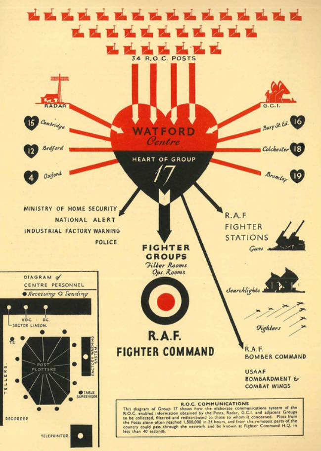
THE ROLE OF THE OPERATIONS CENTRE:
Scan of page from the book "Observers' Tale - The Story of Group 17 of the R.O.C." Published by Roland Brothers, London (1950)
Structure of Operations Room
At each Centre, plotters sat around a large table map called the Main Plotting Board. These plotters had head-sets continuously connected to a cluster of observation posts, usually three in number. The plotting table consisted of a large map with grid squares and posts marked. Counters were placed on the map at the reported positions, each of which indicated the height and the number of aircraft represented, a colour coding system indicated the time of observation in 5-minute* segments as identified from the operations room clock. The table was surrounded by plotters, each communicating with their cluster of posts. Over time the tracks of aircraft could be traced, the colour coding enabled the extrapolation of tracks and the removal of old ones.
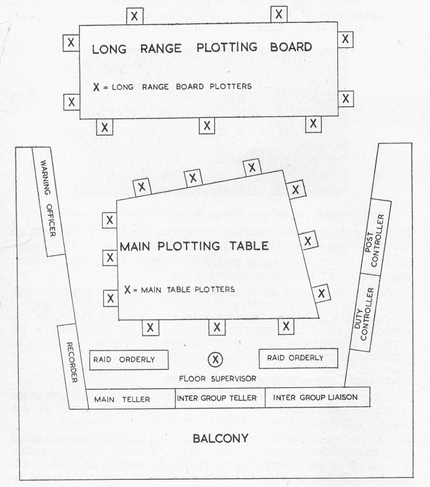
Example of a typical operation room layout c.1945
Originating from 1942, long range boards were introduced to centre operations rooms, so that tellers in contact with neighbouring groups could hand over incoming and outgoing tracks which were plotted on this map.
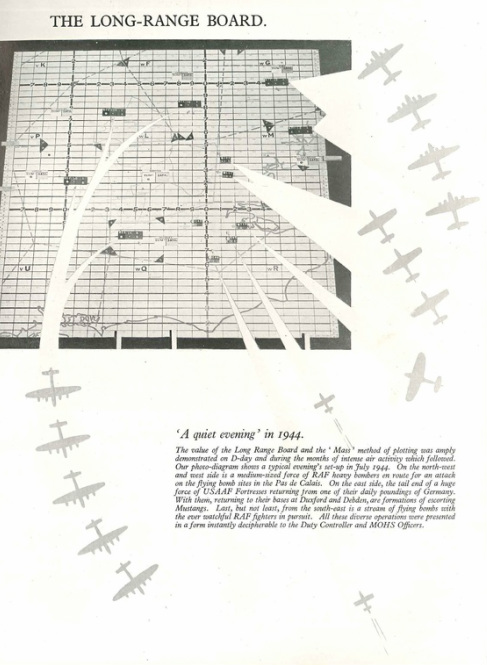
THE LONG RANGE PLOTTING BOARD: Scan of page from the book "Observers' Tale - The Story of Group 17 of the R.O.C." Published by Roland Brothers, London (1950)
Duties
Duties in the operations room included:
Duties in the operations room included:
- Plotters working on the plotting table and on the long range board;
- Tellers communicating with neighbouring ROC groups, fighter operations rooms, anti-aircraft and searchlight units;
- Alarm controllers in contact with the police, national alert system, Ministry of Home Security and with local factories;
- An interrogator liaising with the ground controlled interception (GCI) radar units; and
- Duty Controller, his assistant and a post controller who supervised the plotters and posts.
System of Plotting of Aircraft - Visual Plotting
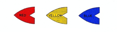
The system of ploting required by the Operations Centre relied upon a clock placed within a prominent position and marked off in 5-minute intervals. Taking any quarter of an hour commencing from the quarter, the first five minute space is coloured RED, the second YELLOW and the third BLUE. Coloured lamps suspended over the table indicated the current colour (and therefore the 5-minute time period) and as a result, representative coloured plotting counters were used to signify the direction that the raid was progressing.
When the plotter receives a plot from a post, they place a counter onto the maps reference square and pointing towards the direction in which the raid is reported to be flying i.e. North, South, East, West etc. This counter must represent the colour represented by the clock period and as indicated by the coloured lamp. After two or more plats had been received, the line of cunters indicate clearly the direction of the raid's track and it was therefore unnecessary to ask Posts for the Direction of Flight. At the end of the 5-minute period the lights were changed to represent the new colour for the respective time period.
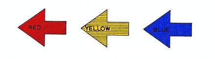
Plotting counters used for Visual Plotting
In addition to the plotting counters, square red and blue counters were used for representing the number of aircraft in a formation and the height (000's feet) at which the raid in flying respectively.
System of Plotting of Aircraft - Sound Plotting
This system relies totally on the expertise of the Observer at the post to accurately report the direction of which an aircraft is heard. As no visual log may be made of the aircraft it would be difficult to gain any indication of height. As such all plots are provided on a circle on a map which has a radius of 5-miles from the post. A single sound plot therefore does not signify the position of the aircraft but merely its supposed direction or bearing from the post. Two such plots from neighbouring observeration posts however may be used to provide an estimate of the position of the aircraft.
Plotting counters used for Sound Plotting
* = As aircraft increased in speed, the time scale used for plotting was reduced from 5-minutes down to 2.5-minutes.
Image Source: ROCA National Archive / ROC Training Manual 1949
Image Source: ROCA National Archive / ROC Training Manual 1949